The same vessel-data sidebar, the same ECDIS palette legend, the same radar PPI hash marks. A working bridge display shows the same fixed user-interface elements every minute of every watch for tens of thousands of hours. That is exactly the duty cycle that drives image retention and, eventually, permanent burn-in on industrial LCD panels. Buyers who only think about brightness, nit count, and ingress rating often miss this longevity question until a year-three refit. Marine display image retention is not an obscure failure mode. It is a procurement variable worth planning around before the helm is wired.
What Is Image Retention on a Marine Bridge Display?
Image retention and burn-in are often used interchangeably, but they describe two distinct failure modes that need different fixes on a marine display.
Temporary image retention happens when a static pattern leaves a faint ghost on the screen after the content changes. Inside an LCD cell, the liquid-crystal molecules slowly drift toward an equilibrium orientation when a voltage signal stays the same for hours. When the content finally shifts, the molecules need time to relax back. The result is a soft outline of the radar sweep ring, the AIS target list, or the vessel sidebar that fades over minutes to hours. This is a recoverable condition.
Permanent burn-in is a hardware change. Two mechanisms drive it on industrial LCDs. The first is differential LED aging in the backlight: areas behind a bright static element age faster than areas behind a darker one, producing a dim outline that never fully recovers. The second is polarizer film degradation, where the same patches of polarizer that handle the highest contrast workload over years discolor slightly. Both changes are gradual and both are permanent.
Marine displays are nearly all IPS or VA liquid-crystal panels, not OLED. Consumer OLED burn-in coverage is everywhere on the web, but the chemistry is different: organic emitter wear versus liquid-crystal drift and polarizer aging. The mitigations are also different, which is why a generic consumer-LCD article is the wrong reference for a commercial bridge spec. Long-running bridge installations also age under bright sunlight at full backlight current, which compresses the retention timeline compared with an indoor office monitor.
The visible symptoms on a marine display are familiar to anyone who has stood a long ECDIS watch. A faint outline of the depth-sounder banner where the sidebar used to sit. A subtle tint on the dashed chart-scale band. A ghost of the radar PPI center marker after the operator switches from radar overlay to clean chart view. Each of these is the same physics. Fixed voltage, fixed brightness, fixed time. Playing out on a different region of the panel.
Why Are Bridge Displays More Exposed Than Office Monitors?
A bridge display does not get the breaks an office monitor takes for granted. Three duty-cycle realities stack on top of each other and compress the retention timeline.
The first is hours. A commercial-vessel bridge display runs twenty-four hours a day for the duration of every voyage, with at-port idling that often keeps the system powered. Eight thousand to twelve thousand hours per year is a routine duty cycle. An office monitor at four hours of true active use per weekday accumulates roughly one thousand hours per year. Compression factor on retention exposure: eight to twelve to one.
The second is brightness. To stay legible against a fully sunlit windshield, a bridge display sits at fifteen hundred to twenty-five hundred nits during daylight watches. That backlight current is six to ten times what an office monitor delivers. Higher current means faster LED aging, more heat dissipation through the polarizer stack, and faster liquid-crystal drift under any given static voltage pattern. The same enclosure that handles the warm sealed marine envelope reliably also runs noticeably hotter at the cell than a cool office monitor, which accelerates every retention-related chemistry.
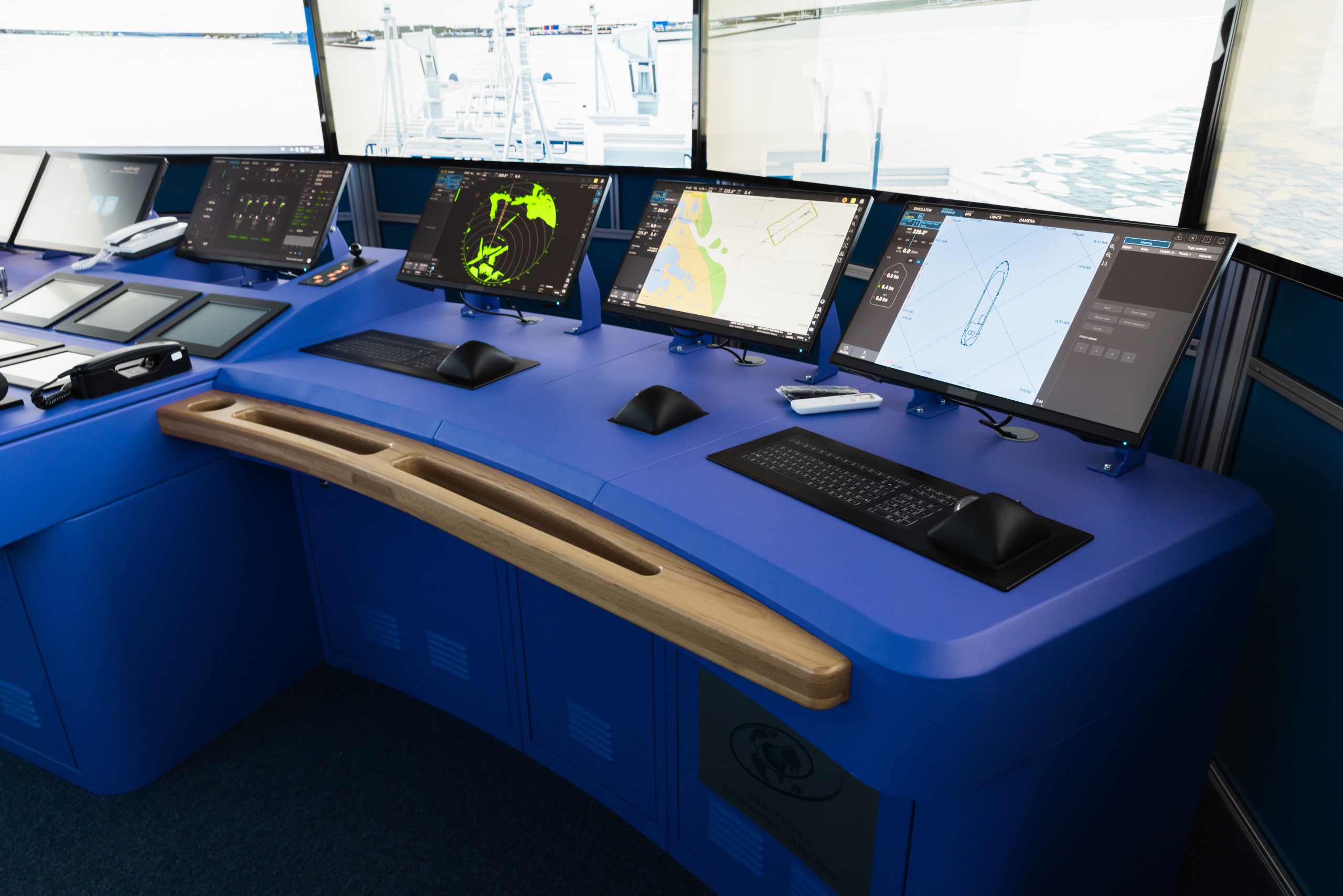
The Static UI Trap on ECDIS and Radar Workstations
The third reality is the worst of the three. Bridge user interfaces are deliberately static. ECDIS standards demand fixed palette legends, course-up versus north-up orientation indicators, scale ribbons, alarm panels, and vessel-data sidebars in predictable screen positions. Radar workstations keep the PPI center, range rings, and EBL/VRM controls in the same place across an entire voyage. The integrated bridge style guides that govern these screens are doing safe-watch work: an operator should never have to hunt for an alarm panel during an emergency. But the same predictability that protects the watch officer punishes the panel.
The combined effect is that the static UI elements run at near-maximum brightness, in fixed positions, at higher cell temperature, for ten to twelve times the annual hours of a comparable office monitor. Image retention shows up earlier in the warranty period, and the slow path toward permanent burn-in is shortened.
Which Hardware Levers Reduce Image Retention Risk?
Procurement teams have more leverage on this problem than they often realize. The hardware levers split into three groups, and each one should appear explicitly on the spec sheet.
Panel grade is the highest-impact lever. Industrial long-life LCD panels are physically different from consumer panels. They use a thicker liquid-crystal cell gap, a higher-purity liquid-crystal mixture, and a polarizer film that is rated for thousands of hours under continuous full-brightness operation. The data sheet should call out an image-sticking specification: typical industrial panels target an image-sticking class of three or four on the JIS standard after a defined burn-in test pattern. Consumer-grade IPS panels rarely publish this number because they were not designed for it. Demand it in writing.
Backlight architecture is the second lever. Direct-lit local-dimming backlights age more evenly than edge-lit backlights because every zone shares the duty cycle. Edge-lit panels concentrate LED current at two strips, accelerating differential aging behind the static UI band. For long-duty bridge installations, direct-lit architecture with binned-uniformity LEDs is the safer choice. Ask for the LED MTBF rating at the panel’s operating brightness, not at a derated test condition.
Driver firmware is the third lever, and it is the one most often missed. Modern bridge displays support several anti-image-sticking features in firmware: dot inversion versus line inversion patterns that break the DC charge accumulation behind static elements, a one-pixel periodic image shift that moves the entire frame on a slow timer, a scheduled full-field refresh cycle that runs during low-traffic hours, and a backlight ramp pattern that exercises every LED zone evenly. None of these features add cost to a panel that already supports them, but they have to be enabled, configured, and documented. The procurement spec should require the vendor to list which features are present and which are on by default.
What to Require on the Spec Sheet
A practical procurement checklist for image retention has five lines. First, image-sticking rating to JIS class three or better at the published operating brightness. Second, LED MTBF at full brightness with a defined ambient temperature. Third, the available anti-image-sticking firmware features listed by name with default-state settings. Fourth, the warranty term against image retention as a covered failure, not as an excluded one. Fifth, the recommended preventive routine for the installation environment. Vendors that cannot answer all five lines are not the right vendors for a twenty-thousand-hour bridge.
A side note: an optically bonded display stack marginally raises the cell temperature because the polarizer is in closer thermal contact with the cover glass, but it also reduces internal reflection and lets the bridge spec a lower backlight current to hit the same legibility. The net effect on retention is slightly favorable for most installations, and the bonded stack is the standard for any bridge that already needs the optical performance.
Which Operational Practices Protect a Bridge Display?
The hardware levers above set the ceiling on how long a panel can last. Operational practice determines how close the installation gets to that ceiling. Five practices show up on every well-managed bridge fleet.
Palette rotation is the highest-leverage operational lever. ECDIS standards require Day, Dusk, and Night palettes that invert most of the static UI colors. A bridge that uses Day-Dusk-Night palette rotation on its standard watch schedule is unintentionally running the best anti-image-sticking program available: every transition changes the voltage state of the static UI cells, which breaks the cumulative charge that drives retention. Bridges that leave one palette running through every watch shorten the panel life noticeably.
Brightness duty cycling is the second lever. Running at full daylight brightness through the night is the single fastest way to accelerate both backlight aging and polarizer wear. The auto-brightness routine should be tuned to drop to the night-watch floor at the right ambient threshold and stay there. A spec target is six to nine percent of peak luminance during dark-bridge operations.
Pixel-shift settings are the third lever. Most industrial bridge displays ship with a configurable pixel-shift period: a few pixels of shift every twenty to sixty seconds. The feature is off by default on a surprising number of installations because integrators worry about chart-position confusion. The shift is small enough that it does not affect chart accuracy and large enough to break cumulative cell charge. Turn it on.
Watch handoff routines that explicitly cycle layouts protect bridges that already have variable layouts available. Switching from a one-radar two-ECDIS layout to a two-radar one-ECDIS layout at noon, or rotating which workstation handles primary chart display, redistributes the static-UI exposure across the panels in the room. This is harder to standardize across an entire fleet but very effective where it can be enforced.
The fifth lever is a quarterly visual audit. A uniform gray test pattern projected on each panel for sixty seconds reveals any developing retention or burn-in that the operators have stopped noticing. Fleets that catch retention early can rotate panels between high-duty workstations and lower-duty backup positions before any single panel is past recovery.
Where Should Marine Display Image-Retention Spec Work Begin?
The cleanest starting point is the installation duty-cycle audit. Walk the bridge, list every static UI element on every screen across a typical voyage, note the predicted annual operating hours, and identify the worst-case static-content zones. That audit feeds three procurement actions.
Specify the panel grade in writing: industrial long-life LCD, image-sticking rating to JIS class three or better, LED MTBF documented at the operating brightness. Require anti-image-sticking firmware features enabled by default, with the configurable options exposed in the OSD. Plan the operational routine before the panels ship: palette rotation on the watch schedule, pixel-shift on, brightness floor configured, quarterly audit on the maintenance calendar.
Seatronx builds the purpose-built marine display lineup around these procurement realities. Bridges that plan retention out of the duty cycle at spec time avoid the year-three refit that is almost always more expensive than the original install line item.
Frequently Asked Questions
Will every marine LCD eventually burn in?
Every LCD that runs static UI elements at full brightness for tens of thousands of hours will eventually show some degree of permanent change. Industrial long-life panels delay the timeline far enough that a well-specified bridge display can finish its twenty-thousand-hour service interval without visible burn-in. Consumer-grade panels in the same duty cycle usually show it within three to five years.
How long does temporary image retention take to clear?
Mild retention typically clears in five to thirty minutes once the content changes. Heavy retention from a long static pattern can take several hours of varied content, sometimes a full warm-cycle of the panel, before the ghost fully fades. If a pattern is still visible after twenty-four hours of varied use, it is no longer retention. It is the early stage of permanent burn-in.
Does turning the brightness down really prevent retention?
Yes, and the effect is large. Brightness drives LED current, which drives cell temperature, which drives liquid-crystal drift and polarizer aging. A bridge that runs at the proper night-watch brightness floor between dusk and dawn easily doubles the panel service life compared with one that stays at daylight brightness around the clock.
Should we cycle ECDIS Day, Dusk, and Night palettes at watch handover?
Yes. Beyond the ergonomic reasons the standard already requires, palette rotation breaks the cumulative voltage state that drives retention behind static UI elements. The default watch schedule is already a strong retention-prevention program, and running it consistently is the easiest discipline a bridge crew can adopt.
Are OLED marine displays an answer to LCD retention?
Not yet, for most commercial and military bridges. OLED has its own permanent burn-in pathway through organic emitter wear, and the high-duty static UI workload of a bridge accelerates it just as much as it accelerates LCD retention. Industrial OLED panels with the brightness and longevity needed for a sunlit bridge are not yet a standard procurement option. Industrial long-life LCD remains the working answer.
How do we check for retention without taking the display out of service?
Run a sixty-second uniform mid-gray test pattern between watches once a quarter. Any developing retention or burn-in becomes immediately visible against the flat gray field. Most bridge displays support this through the OSD test pattern menu, or through a chartplotter screen that can render a single solid color. Document the findings, because repeatable retention in the same zone across audits is the signal to plan a panel rotation.